
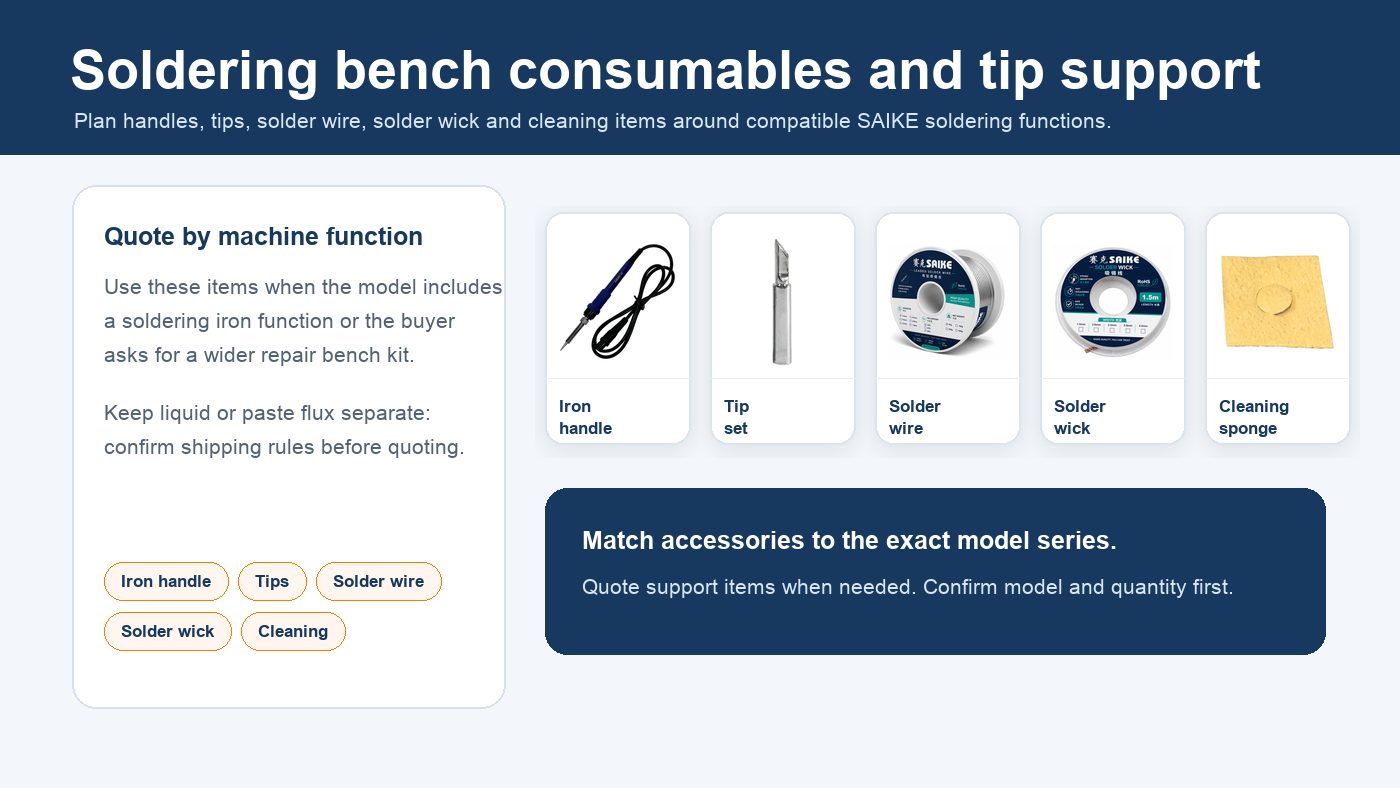
Soldering iron parts usually include the tip, heating element, temperature sensor, handle or barrel, cable and connector. A temperature-controlled soldering station also has a controller, display or adjustment controls, power section and holder outside the iron assembly.
This guide explains the main soldering iron parts and their functions. It also separates replacement parts from working accessories and consumables so buyers can request the correct item without assuming that one part fits every soldering iron or station.
Quick Answer
The soldering tip transfers heat to the joint. The heating element creates the heat. A temperature sensor measures working temperature in supported designs, while the controller adjusts power to maintain the selected setting. The handle, insulation, cable and connector support safe operation and connect the iron to its power or control source.
Before replacing any part, confirm the exact model, handle connector, heater type, tip series, voltage or power requirement and quantity. Similar-looking parts are not automatically interchangeable.
Main Soldering Iron Parts and Functions
| Part | Main function | What to check |
|---|---|---|
| Soldering tip | Conducts heat from the heater to the solder joint and workpiece. | Tip series, shape, dimensions and fit with the iron or cartridge system. |
| Heating element | Converts electrical energy into heat. | Heater type, rated voltage or power, dimensions and model compatibility. |
| Temperature sensor | Measures temperature for feedback control when the design includes a sensor. | Sensor type and whether it is integrated with the heater or tip assembly. |
| Handle and barrel | Holds the heater and tip while insulating the operator from heat and electrical parts. | Connector, cable layout, heater fit, grounding or ESD requirement and station model. |
| Cable and connector | Carry power and, in controlled systems, sensor signals between the iron and station. | Pin arrangement, connector type, cable condition and station compatibility. |
| Tip retaining parts | Secure the tip or cartridge in the correct working position. | Sleeve, collar or retaining design used by the exact iron model. |
| Station controller | Regulates heater power and shows or adjusts the selected temperature. | Control method, supported handle, power rating and calibration or service need. |
| Iron holder | Provides a safe resting position and may include a sponge or brass-wire cleaner. | Holder size, stability and whether cleaning items are included or optional. |
How the Parts Work Together
In a conventional temperature-controlled iron, electrical power reaches the heating element through the cable and connector. The heater raises the temperature of the tip, and the tip conducts that heat to the solder joint. A temperature sensor provides feedback to the controller, which adjusts power according to the selected setting and the heat removed by the workpiece.
The tip does not create heat by itself. Its job is to transfer heat efficiently. Tip condition, contact area and thermal fit therefore affect soldering performance even when the heater and controller are working normally.
Tip Shapes and Working Tasks
Tip shape should match the joint rather than being selected only by appearance. A small pointed tip can reach fine areas but may transfer heat slowly to larger joints. Chisel, bevel or knife shapes provide a wider contact area for connectors, wires, pads or drag soldering when the dimensions suit the work.
- Fine pointed tip: small pads and access-limited work.
- Chisel tip: general PCB joints, wires and connectors.
- Bevel tip: wider heat transfer and selected drag-soldering tasks.
- Knife tip: edge contact and selected SMD work.
The shape alone does not confirm compatibility. Check the tip series and physical fit before ordering.
Replacement Parts, Accessories and Consumables
| Group | Examples | Order handling |
|---|---|---|
| Replacement parts | Handle, heater, sensor, cable, connector and retaining parts. | Confirm exact model and electrical or mechanical compatibility. |
| Working accessories | Compatible tip shapes, iron holder and cleaning tools. | Select by repair task after confirming the correct series. |
| Consumables | Solder wire, solder wick, cleaning sponge, brass wire and selected flux products. | Quote separately according to use, quantity and destination requirements. |
These support items are not automatically included in the standard package of every machine. Check the product package and quotation separately.
SAIKE Compatibility Examples
SAIKE product records show why compatibility must be checked by model rather than by appearance:
- SAIKE 898D, 8586D and 909D product specifications identify a 132A ceramic heating element for the soldering section.
- SAIKE 947 45W and 947 60W soldering iron specifications identify the 900M-T tip series.
- A handle, heater or tip listed for one series should not be applied to another model unless the connector, electrical rating and mechanical fit have been confirmed.
These examples describe documented model directions. They do not mean that every SAIKE soldering iron or station uses the same handle, heater or tip.
Common Symptoms and First Checks
| Symptom | Possible areas to check | Before ordering |
|---|---|---|
| No heating | Power source, cable, connector, heater, fuse or controller. | Confirm the model and diagnosis; do not order a heater from the symptom alone. |
| Slow heat recovery | Tip condition, tip contact, heater performance, power setting or oversized joint. | Check the task and tip contact area before assuming a component failure. |
| Unstable temperature | Sensor, heater, connector, controller or calibration condition. | Provide the displayed behavior, test condition, photos or video. |
| Loose or damaged cable | Cable strain relief, connector and handle wiring. | Stop using visibly damaged equipment and confirm the correct replacement assembly. |
| Poor solder wetting | Oxidized tip, unsuitable temperature, solder or flux condition, or contaminated joint. | Clean and inspect the tip and process before replacing electrical parts. |
Disconnect the equipment before inspection. Electrical repairs inside the equipment should be handled by qualified service personnel.
What to Confirm Before Ordering Soldering Iron Parts
- Complete machine or soldering iron model.
- Photo of the original part and connector.
- Tip or heater series if marked.
- Voltage, power rating or station version.
- Required quantity and whether the order is for repair, stock or a complete support kit.
- Destination country and any consumables that should be quoted separately.
Related Soldering Support Guides
- Use the Soldering Station Parts Checklist when checking handles, heaters, tips and service stock by machine model.
- Read the Soldering Tips, Handles and Consumables Guide for working accessories and optional bench consumables.
- See Repair Kits when machines and support items need to be quoted together.
Need a Compatible Part or Quotation?
Contact SAIKE with the machine model, original-part photo, connector, required quantity and destination country. We can help check the suitable part direction before quotation.